Start stop circuit what they are where and how to wire example of a category 3 scientific diagram basic control circuits motor ladder logic electronics textbook engineering expert witness blog convert wiring plc program realpars electrical technology added new three separate controls two jog tw older air compressor help page diy home improvement forum applied electricity solved activity 5 2 pushon chegg com starters magnetic starter c3controls vfd electrical4u figure 7 13 components way switch dengarden connect reversing or 4 psc gearmotor bodine diagrams do it yourself free editable examples edrawmax online read station controlling 120 volt quora types vehicle for towing multiple push on stations power transformer eep generators with interface phase design a2z question the machinist an allen bradley 709 single 220v hobby build auto rotary converter metalwebnews technical data guide wite installation ac worksheet electric fuel shutoff solenoid 101 seaboard marine float apg going from powerflex 4m drive horizon solutions 5hp baldor 10 30 plugs ok

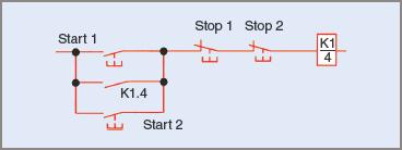
Start Stop Circuit What They Are Where And How To Wire

Example Of A Category 3 Circuit Scientific Diagram

Basic Control Circuits

Motor Control Circuits Ladder Logic Electronics Textbook

Ladder Diagram Engineering Expert Witness Blog

How To Convert A Basic Wiring Diagram Plc Program Realpars
Electrical Technology Added A New

Three Wire And Separate Controls Basic Control Circuits

Two Wire Control Start Stop Jog Circuit

Control Wiring 3 Wire Start Stop Circuit Tw Controls
Older Air Compressor Wiring Help Page 3 Diy Home Improvement Forum

Motor Circuits And Control Applied Electricity

Start Stop Circuit What They Are Where And How To Wire
Solved Activity 5 2 Wiring Three Start Stop Pushon Chegg Com
Motor Control Starters Magnetic Starter C3controls

Vfd Start Stop Wiring Diagram Electrical4u

Figure 7 13 Control Circuit Components

Motor Circuits And Control Applied Electricity
Start stop circuit what they are where and how to wire example of a category 3 scientific diagram basic control circuits motor ladder logic electronics textbook engineering expert witness blog convert wiring plc program realpars electrical technology added new three separate controls two jog tw older air compressor help page diy home improvement forum applied electricity solved activity 5 2 pushon chegg com starters magnetic starter c3controls vfd electrical4u figure 7 13 components way switch dengarden connect reversing or 4 psc gearmotor bodine diagrams do it yourself free editable examples edrawmax online read station controlling 120 volt quora types vehicle for towing multiple push on stations power transformer eep generators with interface phase design a2z question the machinist an allen bradley 709 single 220v hobby build auto rotary converter metalwebnews technical data guide wite installation ac worksheet electric fuel shutoff solenoid 101 seaboard marine float apg going from powerflex 4m drive horizon solutions 5hp baldor 10 30 plugs ok

